
Object Placement
Objective
Prepare all objects you want to print, so your printer can print them. Learn how to arrange them on your print bed. Rotate and scale them to your likes.

Workflow
Open the “Object Placements” tab. You will see the print area on the left side. You start with importing all STL files using the “Add Object” button  . You can select multiple object files at once if you want. This must be in one of the following formats: STL, OBJ, 3DS. The host will always try to position the objects in a non overlapping way onto your bed.
Browsing 3D View
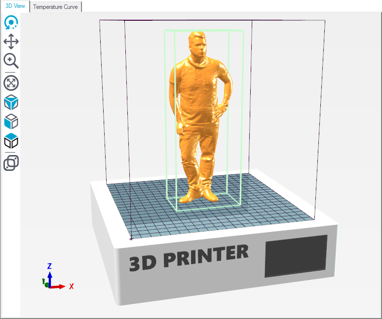
In this window you see your 3D objects. At the left side, you find some navigation buttons:
The first 3 buttons change the behaviour of the left mouse button. Starting at the top, you get “Rotate”  , “Move Object”
  and “Zoom”
  . All funtions can be used with control keys, so that you don’t have to change all the time.
 Control: Holding the control button, you can rotate the view with the left mouse button.
Shift: Holding shift button you can move the view point with the left mouse button.
Right Mouse Button: Move the object by holding the right mouse button.
Mouse Wheel: Zoom view
With this icon  the objects will be zommed to fit exactly in the preview area.
With the next three icons 

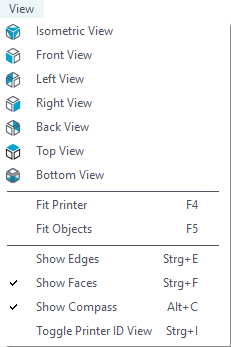
 you can select between predefined view orientations. You find more view options at the top View menu:
Fit Printer (Strg+A): Zooms to fit the complete printer area into the window with maximum size.
Fit Objects (F5): Zooms to fit all objects into the window with maximum size.
Show Edges (Strg+E): Toggles display of triangulation edges.
Show Faces (Strg+F): Toggles display of triangulation faces.
Show Compass (Alt+C): Toggles display of coordinate compass at the left bottom.
Toggle Printer ID Vies (Strg+I): Toggles the display of the printer ID on top of the right tab. Use this to distinguish the printer when you have more than one host running.
“Use Parallel Projection”  toggles between parallel and perspective projection.
Object Placement
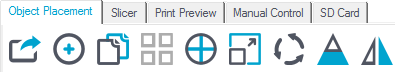
 Here you can export all displayed objects at once. If you save them as .amf file, the object grouping and material assignments remain intact, if you save it as .stl or .obj file, everything gets combined into one object.
 Here you can add objects in .stl, .obj, .amf and .3ds format.
") Here you can duplicate the marked object(s) as many times as you want.
Here you can duplicate the marked object(s) as many times as you want.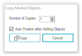
 Click here to place all objects so that they fit on the bed.
 This function centers the marked object in the center of the bed.
") With this function you can scale the marked object.
With this function you can scale the marked object.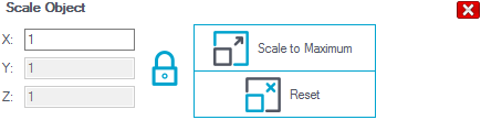
If the lock is closed, all axes are changed simultaneously. If you click on the lock to unlock, you can adjust each axis separately and the object may be distorted. A click on “Scale to Maximum” enlarges the object so that it has the maximum printable size.
") With this function you can rotate the marked object around each axis. Click on “Lay Flat” to place the object flat on the bed.
With this function you can rotate the marked object around each axis. Click on “Lay Flat” to place the object flat on the bed.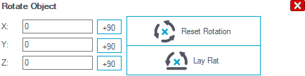
 This option is only used to control the object and has no influence on the print. With “Position” the height of cut position is defined, “Inclination” and “Azimuth” define rotation of the cutting plane.
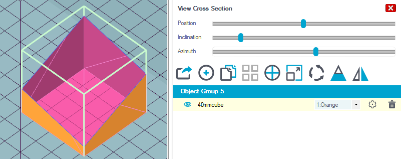
") Here you can mirror objects.
Here you can mirror objects.
Selecting and moving objects
You can select one object by right clicking on it. If you press the ctrl-key while right clicking the selected object is added. ctrl-clicking a selected object removes it from the selection.
To move the selected objects, hold the alt-key down while left clicking and dragging the objects. When you select “Top View” from the left toolbar, the movements will follow your mouse movements. If you don’t, the direction of the move is not the same of the mouse movement.
Depending on your configuration, the object may start to pulse or change it’s color, if it is not entirely on the print bed. This should help you identifying printing problems, even before you start slicing.
Grouping Objects
Object groups are used only for multi extruder prints. For multi extruder prints you normally get one stl file for each color. After you loaded them, each has it’s own group, which normally causes wrong relative positioning. So you need to drag the second stl onto the first stl to merge them into one group. After merging you have to assign each file a separate extruder. Assigning the same extruder will normally cause problems during slicing.
Now it’s time to slice your objects. Open the slicer tab and continue there. More on this in the next chapter.