
How it works
Before you start defining your auto leveling you should know what you are doing and what you can change and where you would change what error.
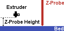
The most important tool is your z probe. That is a device switching a digital pin under some pressure like a switch and is connected to your extruder such
that it triggers normally before the nozzle hits the bed. Once you know the nozzle height above bed when it triggers we can use this to measure how the bed is positioned in z direction.
The first thing we normally do is level out the bed. To do so we measure at least 3 points and compute the average plane trough this. The difference to than theoretically constant z show us how much rotation is required to be everywhere on same height. This can be done through a software rotation (if z moves have no backlash) or through a mechanical movement of the bed sides (through motorized modification of 2 from 3 fix points). This works quite well, but neglects some errors:
- Most beds are not totally flat. Especially under heat they get some bending
- Measurement is not always 100% exact.
- Measurement may bend your bed.
If that is a problem with your printer, you would measure a n x n grid to get a better approximation of the bed.
With z probes that require some considerable amount of force it may bend the bed depending on the position. For this we have a bending correction, that corrects measured values by bending. This is a bit limited especially if bending is not a linear function of x and y. Then you must limit measurements to 3 points for which you set the bending correction.
Even with an average plane for rotation, you still have bumps. With some luck the average bump is negligible and you can ignore it. In more extreme cases, especially with increasing bed sizes, it would be great to be able to follow the curvature of the bed for the first layers and remove that correction to zero with increasing z. That would help a big deal with correct bonding. This feature is called distortion correction and since 0.92.8 it is available for all printer types. It works by measuring a distortion map and storing it in eeprom (ideally) or ram (then you need to measure every time). Also since 0.92.8 we assume that distortion never changes, since it is a bed property. So recomputing the rotation will NOT reset the distortion map.
Z-probe and z-homing
The best solution for printers having a z-probe is to home to z max. This allows rehoming during a print, e.g. if after a pause the motors were turned off and you might not trust your current position. Also you have no problems that a tilted bed hits the nozzle/probe while homing. You would simply home z first then xy and would never hit anything. Simple and save. The only drawback is that you need to home t z max and for printing go down again. This may take 30 seconds and some people thing that is not good to wait 30s also many prints take hours. So they are very sure they want to home to z min.
Well, first thing you must know is that a conventional z min end stop is not working here. Lets take some unlikely extremes to picture that. Lets say bed is rotated so that the left edge is 1cm higher the the right front and the 2 back edges are even 1cm higher. A conventional end stop is the lowest point and should prevent any moves going lower, so in this example it must match the right front edge. If we home Z first we will crash the nozzle into bed at any point except the right front edge. You see that is not a solution, so what you will need is a z sensor that is mounted on your extruder. To tell firmware we want to use z-probe also as z min end stop is by setting both to the same pin! That way we can measure everywhere the height to bed. But that is useless if we do not know where we are measuring, so we have to home x and y first. Ok, no problem if we are at a good height. Why? Well assuming our rotated bed again measuring at low z might cause extruder/probe to collide with the bed. So in version 1.0 newer then 14. January 2017 you can set homing to raise z before homing. Reason is simply to cause no collisions. Sounds simple, but what if are by accident near the top. If you have a z max end stop as well, that would catch the up move simply by triggering and you are safe. If you have no z max end stop just make sure never to move that much up. Ok, point taken, next issue. Now that xy homing is working safely we want to home z. So we have to think about a position where we can home z. Normally this is done at xy home position. But the z probe is in most cases not where the nozzle is plus it must be over the bed to do a valid measurement. So firmware will activate z probe adding offset and measure. SO if you are lucky it works since you home to min x and probe is on left side of nozzle. If not we HOME_ORDER_XYTZ which allows us to set a min. temperature for nozzle (only important if extruder is part of z probe) and more important we can set a probing coordinate. So we move first to that coordinate and then measure the height with offset. That way we can overcome the last problem with z min homing.
Configuring firmware
Z-Probe
Since version 0.90 the Repetier-Firmware supports auto leveling. For auto leveling you need a z-probe to measure the distance in a automatic or semi-automatic fashion. An automatic z-probe is moved with the extruder, so that the firmware does not need to wait for user actions. A semi-automatic z-probe could be a switch used by cnc machines to measure tool height. Because it is not connected with the extruder, you need to position it underneath the extruder and click it once. Then the measurement will begin and after measurement, the extruder will move to the next position and wait for the next signal to start measurement. That way you can have a z-probe, where you do not need to consider on how to fix and activate it. First step is configuring the z-probe in the configuration.h file. Here the according settings part:
/* Z-Probing */
#define FEATURE_Z_PROBE true
/* After homing the z position is corrected to compensate
for a bed coating. Since you can change coatings the value is stored in
EEPROM if enabled, so you can switch between different coatings without needing
to recalibrate z.
*/
#define Z_PROBE_Z_OFFSET 0 // offset to coating form real bed level
/* How is z min measured
 0 = trigger is height of real bed neglecting coating
 1 = trigger is current coating

 For mode 1 the current coating thickness is added to measured z probe distances.
 That way the real bed is always the reference height. For inductive sensors
 or z min endstops the coating has no effect on the result, so you should use mode 0.
*/
#define Z_PROBE_Z_OFFSET_MODE 0
#define Z_PROBE_PIN 63
#define Z_PROBE_PULLUP true
#define Z_PROBE_ON_HIGH true
#define Z_PROBE_X_OFFSET -11.2625
#define Z_PROBE_Y_OFFSET -6.5
// Waits for a signal to start. Valid signals are probe hit and ok button.
// This is needful if you have the probe trigger by hand.
#define Z_PROBE_WAIT_BEFORE_TEST false
/** Speed of z-axis in mm/s when probing */
#define Z_PROBE_SPEED 5
#define Z_PROBE_XY_SPEED 150
#define Z_PROBE_SWITCHING_DISTANCE 1.5 // Distance to safely switch off probe after it was activated
#define Z_PROBE_REPETITIONS 5 // Repetitions for probing at one point.
/** The height is the difference between activated probe position and nozzle height. */
#define Z_PROBE_HEIGHT 39.91
/** Gap between probe and bed resp. extruder and z sensor. Must be greater then initial z height inaccuracy!  */
#define Z_PROBE_BED_DISTANCE 30.0
/** These scripts are run before resp. after the z-probe is done. Add here code to activate/deactivate probe if needed. */
#define Z_PROBE_START_SCRIPT ""
#define Z_PROBE_FINISHED_SCRIPT ""
/* Auto leveling allows it to z-probe 3 points to compute the inclination and compensates the error for the print.
 This feature requires a working z-probe and you should have z-endstop at the top not at the bottom.
 The same 3 points are used for the G33 command.
*/
#define FEATURE_AUTOLEVEL true
#define Z_PROBE_X1 -69.28
#define Z_PROBE_Y1 -40
#define Z_PROBE_X2 69.28
#define Z_PROBE_Y2 -40
#define Z_PROBE_X3 0
#define Z_PROBE_Y3 80
First you enable z-probe (FEATURE_Z_PROBE true) and define the pin, where it is connected (Z_PROBE_PIN). Like with endstops you can set the pullup (Z_PROBE_PULLUP) and invert the signal Z_PROBE_ON_HIGH). Many users like to use the z min endstop pins for this. That is ok, but you should be aware
that this does NOT mean you that you must define z min hardware endstop. It is only the z probe connected to the pin that could be used for this.
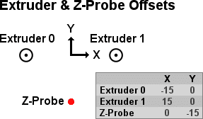
Next you define the offset relative to the extruder origin position (the basis you use to define extruder offsets). For single extruder setup this is the position of the nozzle. For multi-extruder setups the origin, from where you defined the extruder offsets.
If you need to manually move the z-probe, set Z_PROBE_WAIT_BEFORE_TEST to true. In that case, the extruder will hover over the measure points and wait for you to activate the switch once.
Z_PROBE_SPEED sets the probing speed in mm/s, while Z_PROBE_XY_SPEED is the speed in the xy plane. Z_PROBE_HEIGHT is the height difference between z-probe trigger and bed. This value is always added to the height, to compute the total height. Next comes Z_PROBE_BED_DISTANCE, which determines, at which height the probe will start measurements (probe height is added to this). You start with a guessed bed height, which you have set in the firmware. That height minus gap size must always be smaller then the real print area height. If you have some trick to enable/disable a z-probe, you can write the required g-code commands in Z_PROBE_START_SCRIPT and Z_PROBE_FINISHED_SCRIPT. Multiple commands are separated by a \n.
For more precise measurement you can repeat each point Z_PROBE_REPETITIONS times. After a probe is hit, the probe only lifts Z_PROBE_SWITCHING_DISTANCE mm. Depending on your probe type, this can be as less then 0.2 mm allowing very fast repetitions.
Calibrating Z-Probe
One thing that is normally wrong at start is calibration of z probe. So that should be done before you start using it to calibrate everything.
First check is always if signals are correct. So send M119 and see that z probe shows a “L” for low = not triggered. Now trigger it by hand while sending M119 again. Now probe value should show a “H” for high = triggered. If it is the other way around you need to change Z_PROBE_ON_HIGH. If nothing changes you have either the wrong pin used or configured, or pull-up must be different. Fix it and continue.
The most important variable is Z_PROBE_HEIGHT which you normally adjust in EEPROM until it has the correct height. It defines the distance between the nozzle tip and bed
at the time the z probe switches to high. For nearly all types this will be a positive value. Once z probes that use force feedback sensors or have a switch triggered by pressing the extruder have 0 or a small negative value. There are several ways to determine the correct height, but the one I now show is the most accurate I know so it should be preferred. You need a flat metal block where you know the height of the block. The blocks height is our reference height (ref_height). First we go close to the
bed at a distance that the z-probe does not trigger and send a
G30 P0
The returned z height is memorized as z0 for later. Now we heat up nozzle to working temperature and remove all ooze. We leave it at temperature so we measure distance to nozzle tip and not to the end of hardened plastic. Now we send
M114
And note the z height as Zold. Next we adjust z until the metal block fits exactly below the nozzle. You will see that when you have a gap you can easily rotate the block. If you are too low, it will give a “clong” sound when you press bed down. This makes it much more exact then the typically used sheet of paper. Once you think you found exact level, send M114 again and note it a Znew.
So what we now have is starting height as firmware would assume it from first probe Z0 using our initial Z_PROBE_HEIGHT (ZHold). We also know that we needed to go up Znew-Zold to reach ref_height. From this we can compute the exact real value required from Z_PROBE_HEIGHT (ZHnew):
ZHnew = ZHold - Z0 - Znew + Zold + ref_height
Enter this value in eeprom and your measurements will be as precise as you can get it.
Hints: This works fine if you have always the same bed and bed coating. Inductive sensors measure distance to the metal bed part, so it would be possible to correct different bed coatings that you can but on it. The current thickness is stored in Z_PROBE_Z_OFFSET (bed coating in eeprom) and should be 0 for most printers.
Autoleveling
Now that we have a working z-probe, we enable auto leveling. For that you need to add “#define FEATURE_AUTOLEVEL 1”.
Then we define how we want the auto leveling to work. First we define how to measure the plane rotation. Currentyl 3 methods can be defined and set with BED_LEVELING_METHOD.
BED_LEVELING_METHOD 0
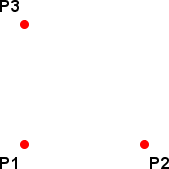
This method measures at the 3 probe points and creates a plane through these points. If you have
a really planar bed this gives the optimum result. The 3 points must not be in one line and have
a long distance to increase numerical stability. Delta printers should have them as close to the columns as possible.
BED_LEVELING_METHOD 1
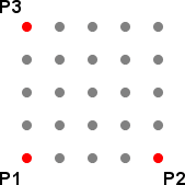
This measures a grid. Probe point 1 is the origin and points 2 and 3 span a grid. We measure
BED_LEVELING_GRID_SIZE points in each direction and compute a regression plane through all
points. This gives a good overall plane if you have small bumps measuring inaccuracies.
BED_LEVELING_METHOD 2
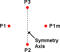
Bending correcting 4 point measurement. This is for cantilevered beds that have the rotation axis
not at the side but inside the bed. Here we can assume no bending on the axis and a symmetric
bending to both sides of the axis. So probe points 2 and 3 build the symmetric axis and
point 1 is mirrored to 1m across the axis. Using the symmetry we then remove the bending
from 1 and use that as plane.
Next you should decide on the correction method. This correction is defined by BED_CORRECTION_METHOD and allows the following values:
BED_CORRECTION_METHOD 0
Use a rotation matrix. This will make z axis go up/down while moving in x/y direction to compensate
the tilt. For multiple extruders make sure the height match the tilt of the bed or one will scratch.
BED_CORRECTION_METHOD 1
Motorized correction. This method needs a bed that is fixed on 3 points from which 2 have a motor
to change the height. The positions are defined by
BED_MOTOR_1_X, BED_MOTOR_1_Y, BED_MOTOR_2_X, BED_MOTOR_2_Y, BED_MOTOR_3_X, BED_MOTOR_3_Y
Motor 2 and 3 are the one driven by motor driver 0 and 1. These can be extra motors like Felix Pro 1
uses them or a system with 3 z axis where motors can be controlled individually like the Sparkcube
does.
You need also to set the following parameter:
#define ENDSTOP_Z_BACK_MOVE 5
#define Z_HOME_DIR 1
The first makes the z-axis go down a few mm after hitting the endstop. This is needed, because we assume a not even bed and correct z height during x-y-travel. It is important not to hit the z-endstop during these travels or your coordinate system gets wrong. The value must be larger then the maximum height difference of your bed. Delta printer user have a special problem at z max. There it is not possible to move the extruder without hitting an endstop. Printing at that height is also not possible for the same reason, so it is a good idea to set ENDSTOP_Z_BACK_MOVE to even higher values where some movements are possible like 50mm. Remember that a slight bed tilt also needs a side move! The second sets homing to z-max. This again is required, because the bed is not planar. If we had a z-min endstop, it should only get triggered where the bed has it’s lowest point. Of course this would mean, that for all other positions homing to z-min would crash the extruder head into the bed.
Verify z-probe
Before you risk any damage, you should test, if you have configured the z-probe correctly. Run a
G31
to check the signal of the z-probe. It should be low/off. Now trigger it by hand and send the command again. Make sure the signal is now inverted.
Next home and measure the distance between extruder and bed. Some commands like G30/G32 will go to a lower position when started, namely Z_PROBE_BED_DISTANCE + Z_PROBE_HEIGHT, so make sure that is everywhere above the bed!
Now that this works, make your first real probe. Move your extruder to a position you want to measure and send:
G30
The extruder will now descent, until the z-probe gets triggered and then go back to the starting position. In your log, you should then find the distance needed to trigger the z-probe. For a first test you may start with plenty of room and trigger the switch manually, just to test if it reverse, which should be the case if you set up the probe correctly. If you have a semi-automatic z-probe hit the probe first to start probing.
Automatic correction
Now that everything is configured and working we can start adjusting the bed. Before using the leveling commands you need to at least home x and y axis. Deltas will home on G32, so they can skip this. Depending on the measurement method you have more or less testing points and time can be greatly reduced if we have to move less in z direction. When we have homed also in z axis the probe gets positioned at Z_PROBE_BED_DISTANCE + Z_PROBE_HEIGHT (if positive). You should select
Z_PROBE_BED_DISTANCE such that it is higher then every expected tilt. If you have only homed x and y as you do not want to home to max z for the time it takes, you should know that the height you enabled the printer is 0 internally until you home. So positioning will be normally higher.
One simple method is G29. It will measure 3 heights (at probing points) and use the average as printer height. This requires homing to z max before starting it.
The much better solution is to correct the possible rotation. We have already defined how we measure and how we correct, so there is no real difference any more. The command to start autoleveling is G32 with optional Sx parameter. What then happen is the following procedure:
- Disabling distortion correction and autolevelig. Autoleveling rotation matrix gets reset.
- Delta printers will home and go down again to starting height.
- If you are higher then max. starting height the probe will lower to that height.
- Measuring and correcting rotation.
- If you have a max z endstop and parameter S was not 0, we update the printer height so later homing gives correct results. Make sure to do this only IF you had homed to z max before or you get completely wrong heights.
- Update current position.
- Store new matrix in EEPROm if parameter S is 2 or higher.
- Enable automatic correction.
- Enable distortion correction if it was enabled before.
- Nonlinear printers like deltas will home again to get right positioning.
Older firmware versions (< 0.92.8) had S1 for measuring and update z length. This is now done always for z max homing as long as S is not 0.
Delta printer
Important: Newer firmware versions (greater than 0.92) use G33 for distorsion correction instaed of G29.
Delta printer need more calibration then normal cartesian printer. You need to calibrate the endstops first. This calibration changes the values you see in the eeprom configuration as “Tower X endstop offset [steps]” resp. Y and Z. The trick is simple. After homing to the max endstops, the firmware will move these steps down to position the extruder holder in the exact center. It is essential to define the exact center position or the nonlinear behavior of delta mechanics will result in wrong geometries. Measuring these values on your own is nearly impossible, so you need to use a simple trick. First home and remove any extruder offset using these commands:
 G28
 G131
Now position the 3 sliders, so that they are at the same height. To do this I use a stick and position all sliders, so that they press the stick lightly against the printer top, as I know it will be centered then. Depending on your printer it might be better to measure from the bottom (not the bed – that might be skewed in addition). The hard way is to use moves in x,y,z direction. The easy way is turn motors off with “M84” and slide by hand. Be careful not to slide fast. Movements create a current in the motors flowing back to the electronics. Since some printers will move down when motors are disabled, newer versions have a command to only disable one motor for a time. So now the best way is to use M99 X0 to move the X motor for 10 seconds. You can change the time with S<time in seconds>. Use Y0 and Z0 for the other 2 axis. Once all sliders are at the exact same height, send:
G132 S1
That will measure the required offsets. S1 additionally stores the result in EEPROM, so you do not need to repeat it again.
After the endstops are calibrated, you can run the bed leveling routine the same way as for cartesian printers.
Enabling and disabling autolevel
Once you run auto level G32, the firmware switches to auto level mode. If you stored it in EEPROM (adding S2) it even survives printer restarts. Then new leveling is only needed if you have to assume that bed has changed the height. You can change this with:
M320 ; Activate auto level temporarily
M320 S2 ; Activate auto level permanently
M321 ; Deactivate autolevel temporarily
M321 S2 ; Deactivate auto level permanently
M322 ; Reset auto level matrix
M322 S3 ; Reset auto level matrix permanently
If you reset the auto level matrix you have the same behavior with enabled and disabled auto level.
Distortion correction
With some luck you are already finished. If your bed is not 100% flat or for delta printers, if your geometry description is not 100% correct you still have different heights between bed and extruder nozzle. Since 0.92.8 this can be corrected using a distortion map. What we do is that we measure a fixed grid of n x n values and store the difference between theoretical height and measured height in a bump map in eeprom (or in ram, but then you need to repeat that every time). This is done using the G33 command. It will measure a grid as you have defined it in your configuration. Start this command only if your z is set correctly. After it is finished, it enables distortion correction. Now your nozzle will also follow the bumps. With increasing z it will reduce the correction until it does not correct z any more.
Note: Distortion correction uses 32 bit integer math. If the z change in steps multiplied by point distance in steps is larger then 2^31 computations will overflow and result is undetermined. In real live with typical corrections this is not hit, but when testing with some big z changes on high resolution printers it gets possible to exceed that limit!
G33 has also 3 special commands.
List bump map
With G33 L0 you will get a listing of all measured bumps and the stored correction. These values get added to z at the respective positions and between the points z correction gets interpolated.
Adjust bump map
G33 X<xpos> Y<ypos> Z<newCorrection>
will set a new correction value to the closest stored position. So you do not need to enter the exact position from the G33 L0 list.
Reset bump map
G33 R0
will set all corrections to 0.
Switching distortion correction on/off
M323 ; Show if correction is enabled
M323 S0 ; Disable correction
M323 S0 P1 ; Disable correction permanently
M323 S1 ; Enable correction
M323 S1 P1 ; Enable correction permanently
Manual Bed Correction
The alternative is to level the bed, so it is square to x-y-moves. This requires less computations and also does not wear out the z-axis as much as the auto leveling (this is equal to mechanical auto leveling). The only drawback is, that it is more work to set it up as good. The easiest solution is with beds supported by only 3 points. In that case you make the 3 measurement points identical to your bed supports. The method is quite simple. You send “G29” and the firmware will measure and output the heights at the three points. Then you change your bed to make them identical and retry. If you are satisfied and if you have a z-max endstop you can also send a “G29 S2” to measure the print area height and store it in eeprom (S1 will only measure the height).