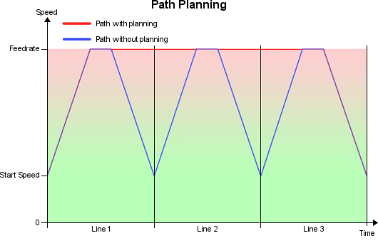
Jerk is what makes your printer shake. It is a speed difference between two moves, which can be reached
without acceleration. So why do you want jerk and what does it influence? The first thing it influences
is the starting speed. It is 50% of the allowed jerk. So if you have a jerk of 20, the first move will
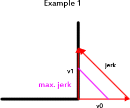
start with 10mm/s. The other thing jerk controls is the join speed for consecutive segments. In the
figure above you see two examples. The jerk is the difference of the two speeds. Example 1 shows a jerk,
that is higher then allowed. In this case, the path planner will reduce the speed to match exactly the
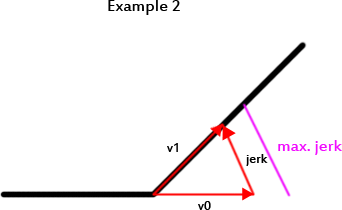
maximum allowed speed. Example 2 has a lower directional change, so the jerk is within allowed limits
and the planner allows a full speed move through the edge. The jerk is set these two values:
#define MAX_JERK 20.0
#define MAX_ZJERK 0.3
MAX_JERK is for x/y axis moves and MAX_ZJERK for moves in Z direction.
You want high jerk values, because
- printing time is reduced.
- print shows less blobs.
You want low jerk values, because
- it causes less mechanical stress to your printer.
- moves are smoother.
- filament has better adhesion at directional changes.
- reduces printer noise.
- you loose steps with higher values.
You see, it is balance between your personal priorities. The only simple thing is z-jerk, which has
nearly no influence. It only reduces the time for z-moves, but has no effect on quality.